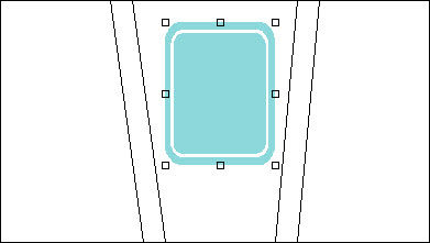
| Add Rectangle
|
Used to draw rectangles in the design area. Once
drawn, rectangles can be resized via their edit handles, moved by selecting
them and dragging them, and their properties can be changed (Color, Filled,
Fill Color, etcetera).
|
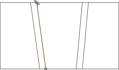
| Add Line
|
Used to draw lines in the design area. Once drawn,
lines can be resized via their edit handles, moved by selecting them and
dragging them, and their properties can be changed (Color, Line Width,
etcetera).
|
| Add Icon
|
Used to add a generic icon in the design area. Once
added, icons can be resized via their edit handles, moved by selecting them and
dragging them, and the icon properties can be changed (Icon, Bring to Front,
Send to Back).
|
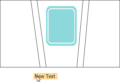
| Add Text
|
Used to add text in the design area. Once added,
text can be edited, moved by selecting it and dragging it, and the text
properties can be changed (Color, Text, Bring to Front, Send to Back).
|
| Show Grid
|
When on, a grid system is displayed. When off, the
grid system is not displayed.
|
| Properties
|
Located in the left panel, the
Properties list is a default listing of the
"required properties" associated with the base
HVAC components and/or compound HVAC components that make up the compound HVAC
component.
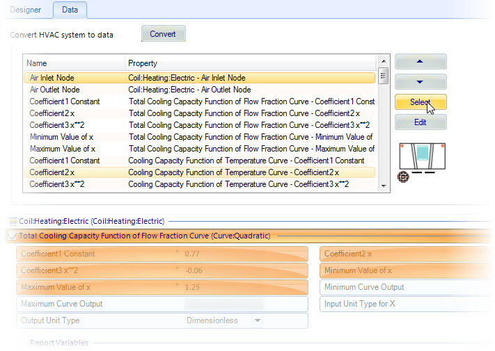
Properties can be added or removed by pressing the
Select button in HVAC
Manager Data
tab. Removing required properties from the Components list here also removes
them from Component Designer, but does not change the requirements. The
properties still must have values. You can optionally set a value, and then
remove the required property from the list.
Connection nodes can be added to the schematic by dragging
and dropping small circular icons from the Properties list. Once added, icons
can be resized via their edit handles, moved by selecting them and dragging
them, and the icon properties can be changed (Color, Line Width, Bring to
Front, Send to Back).Connection nodes are linked to their component properties.
When connections are made to and from these links in the HVAC Manager Designer
mode, the component properties are automatically updated.
|
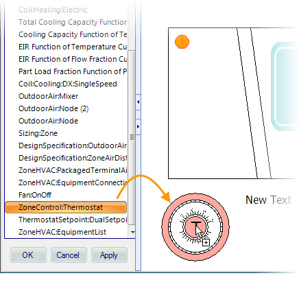
| Components
|
Located in the left panel, the
Components list is a listing of the base
and/or compound HVAC components that make up the compound HVAC component.
Components can be added to the schematic (as sub-components) by
dragging and dropping their icons from the Components list. Once added, icons
can be resized via their edit handles, moved by selecting them and dragging
them, and the icon properties can be changed (Icon, Bring to Front, Send to
Back).
|
| Color
|
Used to change the color of selected elements in
the design area.
|
| Filled and Fill Color
|
Used to fill and change the fill color of selected
rectangles in the design area. Checking Fill enables Fill Color.
|
| Line Width
|
Used to change the line width of selected elements
in the design area.
|
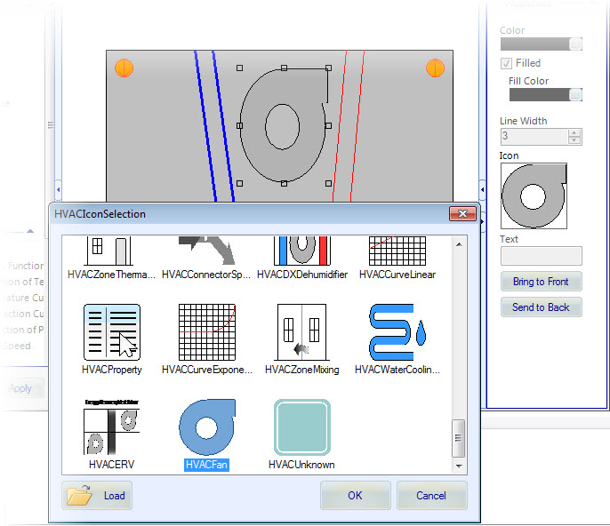
| Icon
|
Used to change the icon displayed for components.
Clicking Icon opens the HVAC
Icon Selection dialog, which
- Icons list –
Contains predefined icons representing various HVAC component types.
- Load – Used to load
external image files to use as icons. Clicking Load opens a browser dialog with
the file filter set to All Supported Image Type.
- OK – Applies the
selected icon, and dismisses the HVAC Icon Selection dialog.
- Cancel – Dismisses
the HVAC Icon Selection dialog without saving any changes.
|
| Text
|
Used to edit text in the design area.
|
| Bring to Front
|
Used to display the selected schematic element on
top of all other schematic items.
|
| Send to Back
|
Used to display the selected schematic element
behind all other schematic items.
|
| OK
|
Applies all changes and closes the Component Designer dialog. The new schematics are
available in HVAC
Manager HVAC Systems tab and in Designer
toolbox.
|
| Cancel
|
Closes Component
Designer without saving any changes.
|
| Apply
|
Applies all changes but does not close the Component
Designer dialog. The new schematics are available in HVAC
Manager HVAC
Systems tab and in Designer toolbox.
|